Wednesday, June 15, 2016

Static shielding and how some online sellers are hurting the maker community

As a maker with an embarrassing number of years of electronics experience, I am a little concerned by the haphazard way many makers handle their projects. Better understanding of how sensitive many electronic devices are can save us hours of pondering over glitches, and can help ensure the projects we spend so much time working on survive long enough to be really useful. You are going to be opening up your Wink hub to connect directly to it, you should observe proper anti-ESD precautions to avoid damaging it. ICs that must connect to the outside world often have rather robust ESD protections designed in, but once you open the case up and start poking around, you may find that the internal connections are more easily damaged by static discharge. It only takes 50V to arc over a MOSFET gate. Your body can easily develop hundreds or even thousands of volts, depending on humidity, clothing, shoes, flooring, etc. Creating a static charge is as simple as touching one object to another and then pulling away. This could be fabric, plastic, metal, cork, carpet, wood, the plastic body of an IC or insulation on a wire, fur, hair, rubber, etc. There are some basic precautions you can take without spending a lot of money on an entire ESD dissipative workstation. However, considering the fact that you are already embarking on a process of learning electronics, an ESD mat is a very good investment. Small desktop ESD dissipative mats can be bought for $15 to $25 at local office supply stores or online. Get a wrist strap, too, if it isn't included. Do NOT buy a "wireless wrist strap" or any other device that claims to remove static charge wirelessly, they are provably ineffective. This is a black static conductive, ESD draining silicone mat. The blue silicone mats are NOT ESD conductive. This one is, I tested mine and it is within specifications. It includes wrist strap and adapter to plug into a grounded outlet.


Silicone black ESD conductive mat Connect the ground cord of the mat to a reasonable ground. The screw on an AC outlet, the ground connection on an AC outlet, or a metal water pipe. It isn't enough to just connect to something metal, that is worse than not connecting to anything at all. If you have a metal outlet strip, the metal body should be grounded when it is plugged in. Connect the wrist strap wire to the ground connection on the mat, then put the wrist strap on. Now set your Wink Hub on the mat and you can take it apart and work on it. To solder wires in, you should be using a grounded soldering iron or soldering station. More information on electrostatic discharge, protections, and procedures: http://www.esda.org/fundamentalsp1.html http://www.minicircuits.com/app/AN40-005.pdf http://www.ti.com/lit/an/ssya010a/ssya010a.pdf ESD Protection Webinar: http://www.digikey.com/videos/en/v/ESD-protection-Webinar/1680491988001 So you don't think modern electronics require ESD protection? http://electronicdesign.com/power/esd-smartphone-s-worst-enemy Dave Jones of EEVBlog did an episode testing the efficacy of silvery static shielding bags versus pink antistatic bags, illustrating how antistatic bags merely don't generate a charge of their own but provide no protection. https://youtu.be/imdtXcnywb8 Video at top of page.

Saturday, May 28, 2016

Digital Photography and Composites on an Amiga computer

Back in the mid '90s, I built a digital photography/compositing business around an Amiga 3000. There was even an interview with me published in Amiga Format magazine.

The Amiga 3000 was a great machine. I was using a desktop A3000 with a MicroniK case that gave me a lot more Zorro III and bridgeboard slots. At first, I used a video camera to capture still images, but that just wasn't high enough resolution for print. So as what I was doing expanded, I eventually ended up with a Phase 5 68060 accelerator and Cybervision 64 graphics card and a Polaroid digital camera that captured 1600x1200 tethered via the SCSI bus. Massive 128MB of RAM, a 1G Seagate SCSI, a 4G Fast SCSI 2 Micropolis AV drive on the Amiga SCSI bus, and a 4G Wide SCSI 3 Micropolis AV drive on the accelerator SCSI bus.

No Amiga drivers for the digital camera I was using (Polaroid PDC-2000), so I ran Shapeshifter and captured with Apple's Mac OS, System 6 (or 7, don't recall now). Since no Mac ever had a 680x0 greater than a 68040 and the PowerPC Macs at that time emulated the 68k chip, my Amiga was faster as a Mac than any Mac. How much faster? When I had the camera demo'd to me in Seattle on a PowerPC Mac, it took nearly 10 minutes to transfer an image from camera to computer. But my 68060 Amiga 3000 took about 15 seconds.

We went to sci fi conventions and composited people into custom backdrops in their costumes. I'd have an inkjet printing out a high res glossy, which took about 15 minutes then, while I had Real3D (a 3D modeling/rendering program) rendering several scenes or elements in the background, while working on a multiple layered graphic at 2400x3000 pixels in ImageFX, then I'd pop over to Shapeshifter to snap someone in their costume while my wife posed them. Printing and rendering continued uninterrupted, and everything ran smooth as silk.

The first Norwescon that we took this to, I had six different Microsoft programmers watch me and talk to me while I was working, and they'd suddenly say "Bill Gates ruined software!" after finding out that I was doing all of this on one computer running at 60MHz.

Between conventions, we'd work from home. I also repaired computers, especially Amigas, and other electronics. For a few years, we also had a science fiction collectibles store.

I had a Primera Pro dye sub printer that required an absolutely uninterrupted stream of data from the computer or the print would be ruined. If you were running Windows, it was best to make sure nothing was running but the print driver, and don't touch the mouse or keyboard. I talked to other people using this printer with Windows 95 on Pentium 100 and up who had prints ruined because they moved the mouse, and it might take 20 minutes to over an hour for the computer to process the file for printing.

It took my Amiga 3000 almost exactly 60 seconds between when I hit Print and the printer started. I tested it really hard one day - I hit Print, then quickly started Real3D and set three different high res 2400x3000 pixel images rendering, dialed into my ISP, started my web browser and opened a dozen tabs on different websites. The result? It took 2 minutes before it started printing, and the print itself was flawless. At no time did my typing or mouse pointer get jerky.

My old website is still up, although the digital photography business is gone. I never took orders online, so no shopping cart. Before you look at it, keep in mind that I never claimed to be an artist.

http://www.polyphoto.com

Hello, Hackaday viewers! If the above website doesn't link, please try again in a bit. Turns out there was a problem with the nameservers. I've fixed it, but it may take a few hours for the changes to propagate.

http://hackaday.com/2016/06/05/how-an-amiga-graphics-business-ran-in-the-1990s/

Update:
I’m inordinately excited – I was cleaning out my storage, and discovered that a friend of mine had given me an A3000, still in the original box! It needs a SCSI hard drive, and I think I have some RAM ZIP chips to max it out (it has 12M now, I think), and I am sure it could use a recapping… but… the battery DID NOT LEAK!
I have a 1G SCSI drive in a removable drive to install in it. I also found I have Kickstart 3.1 chips for it, and both Workbench 3.1 floppies and Workbench 3.9 on CD. I have a portable SCSI CDRom drive. I still have CD reader/burner software. Most of the other software is gone, however I kept a disk image of my original hard drive installation including Directory Opus and ImageFX 3.something.
I find I’m ridiculously excited about this.

Saturday, February 20, 2016

Electric and Magnetic Field Demonstration Box

I'm a member of a maker club in Olympia, WA called OlyMEGA. Sometimes we get invited to display things at science fairs, maker faires, etc. It is always a mad scramble as our members may or may not have a project far along enough to display, yet not installed somewhere permanently yet.

I've been saying for a while that we need to have some things on hand just for those events. When we got asked to do some teaching displays related to magnets for a local children's museum for their adults only event called Love and Magnets, I decided it was time to put my money where my mouth is.

I have done science demos for my wife's kindergarten class over the course of a few years. The electricity and magnetism demos required that I bring a selection of power supplies, parts, and wires. So this first project is to replace all those separate power supplies with one box that can be just opened and used.

It is being built into an old plastic shell carrying case for a camcorder. Clear acrylic panels are used so that you can see the inner workings. A Crookes Tube is going into the lid. A Crookes Tube has a vacuum with an electron beam that hits a phosphor coated angled surface, so that you can see how the beam is bend by electric and magnetic fields.

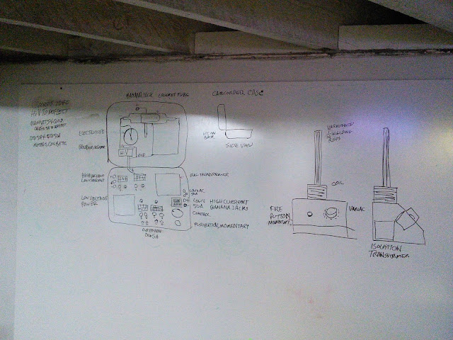
Early sketch of the case. Proposed electromagnetic ring launcher on the right.

I did a lot of measuring of parts and some drawings in CorelDraw, then they were cut and engraved with a LASER cutter. I mismeasured the corners, so I had to round them out a bit more on a belt sander.

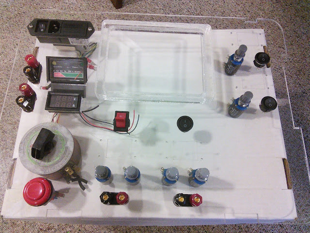
Control panel with some parts installed. Center top is a cap to allow a rather large transformer to fit.

At top left is the power input, including an On-Off switch, fuse, and internal LC noise filter. The two pairs of 30A rated banana jack 5 way binding posts on the left are high current adjustable AC and DC outputs. The analog meter is AC current from the battery charger, the digital display just under it is DC voltage and current. Just below is a variac (variable transformer) good for about 2.5A. The variac then connects to a transformer out of a Harbor Freight battery charger that has a 75A starter boost function. The red pushbutton is so the high current output cannot be left on. I don't know which limit I'll run into first, but I'm hoping for a few 10s of amps into very low resistance.

That might sound impossible with a variac rated for 2.5A, but that will be before the transformer. The voltage drops by the turns ratio, but current rises by the turns ratio. So a 10:1 transformer with 2.5A coming in will net 25A out of the secondary. The transformer is wound with the primary on the inner core, then spacing, then the secondary around the outside of the core. So if the windings present are not sufficient for my needs, I could remove the secondary and rewind it with fewer turns of much heavier gauge wire. Power is my limiting factor, the variac is rated at a max of about 250VA.

The two sets of banana jack 5 way binding posts along the bottom are for medium voltage, medium current use. Both with have round black power switches once another order of them comes in. These outputs are for lower power things like small coils, electromagnets, motors, etc.

I think the blank area on the bottom right is going to get a hole cut for a cooling fan, and I now have a short-resistant class C audio amplifier to add, although I think I'll place a 2 ohm 10W resistor inline so as not ot unnecessarily stress the amplifier. I have a coil wound around a film canister and hot glued to a paper plate. It is very effective to demonstrate how a speaker works by turning up the amplifier and then lowering it over a neodymium magnet.

Continuing clockwise, two more switching power supplies with digital readouts. Both will be connected to 3V to 7kV high voltage converters that will be added to the feedback path with voltage dividers. The one at the top right is to supply the Crookes Tube, the one just below it will have both a positive and negative high voltage up to about 5kV to be used to bend the electron beam with an electric field, and for external devices that require high voltages. The outputs of the positive/negative high voltage are in the panel in the lid. I have determined that the outputs of the 3V to 7kV high voltage converters are isolated, so I can merely connect the positive of one to the negative of the other and ground that junction.

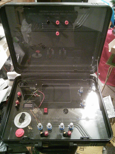
The panels in the case. Nothing else is installed yet.
The Crookes Tube is going in the top just under the safety banana jacks. The lone red jack in the middle will connect to a smooth, flat electrode just above the Crookes Tube and to a needle electroscope. This can then be used to illustrate that like charges repel, unlike charges attract, and how sharp points and ultraviolet light can drain charge. The safety banana jacks above are to be changed so they will be left yellow for negative, center green for ground, right red for positive from the 0 to 5kV supply. This will then also be available for electroscopes, static electricity motors, etc.

Everything but the high current outputs will be powered from an open frame 12V@15A switch mode power supply which I bought surplus. I bought several of them a few years ago to power a solid state cooler, and bought a few extra.

Another carrying case will store things used with this to illustrate the concepts. Magnets, electromagnets, coils, various kinds of DC and AC motors, etc.

I will post updates as the project progresses.